Spring 2022 Robotics Class.
A robot is machine that can sense and move in a way that emulates the actions of a living thing. Projects ordered from latest to oldest.
Cake Baking Robot
For our final project, my intro to robotics class was tasked with a team challenge to build a robot system that would bake a cake and frost and image onto the cake. The overrall systems breakdown was:
Mix the cake batter and pour it into a pan
Load the pan into a conventional oven
When the cake is baked, unload the cake and load it to a mechanism that would frost the image
Frost image onto cake, without prior knowledge of the image (no hard-coded solution).
The class was split up into different subteams to tackle on the project. I chose to join the Oven Control team as Project Manager. My role was to organize the design of our solution for autonomously setting up the oven so that the cake could be baked. I made use of my experience in the class of consolidating various solutions and ideas and tried my best to come up with a solution that me and my partners would be proud of.
Design
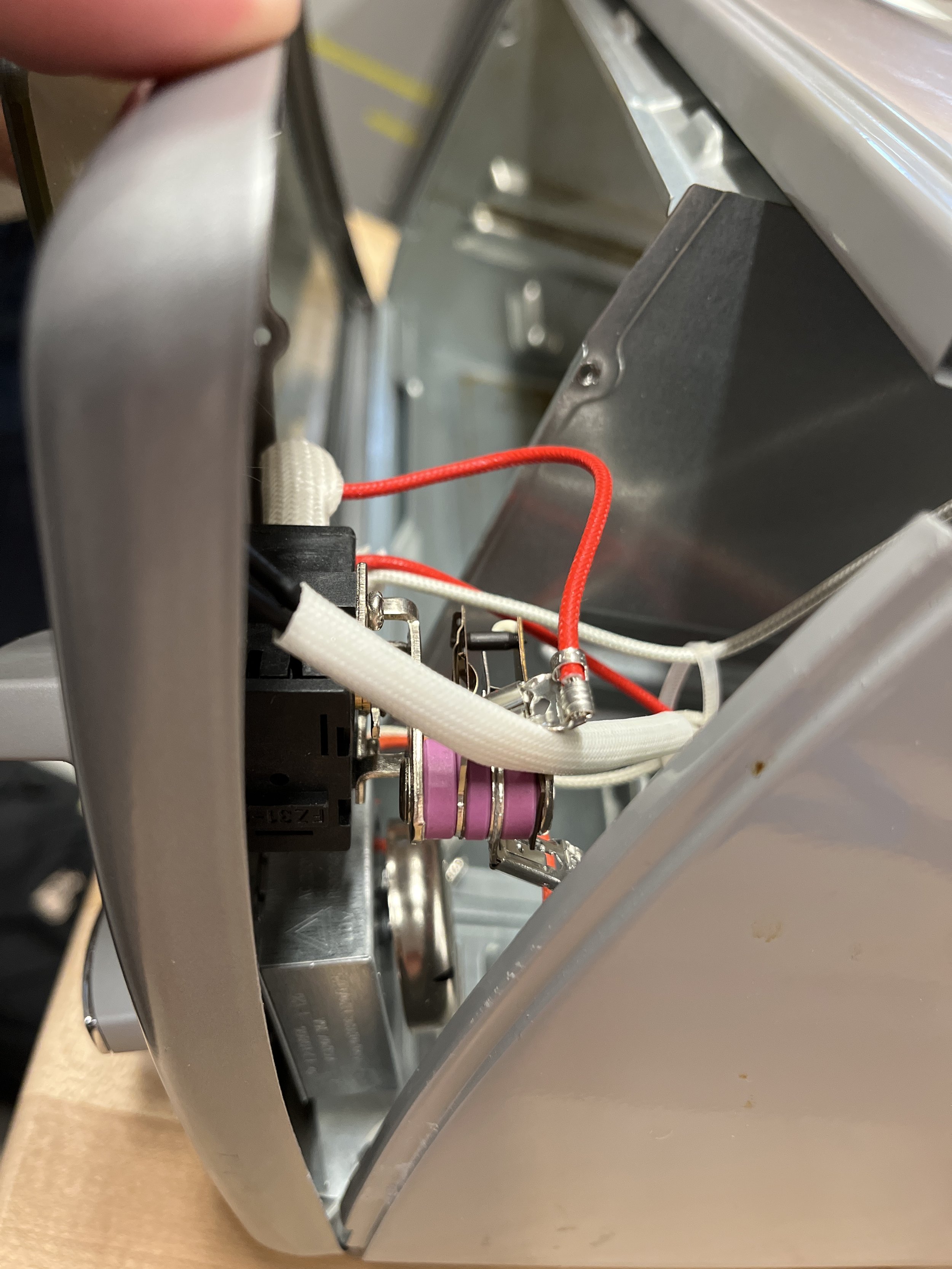
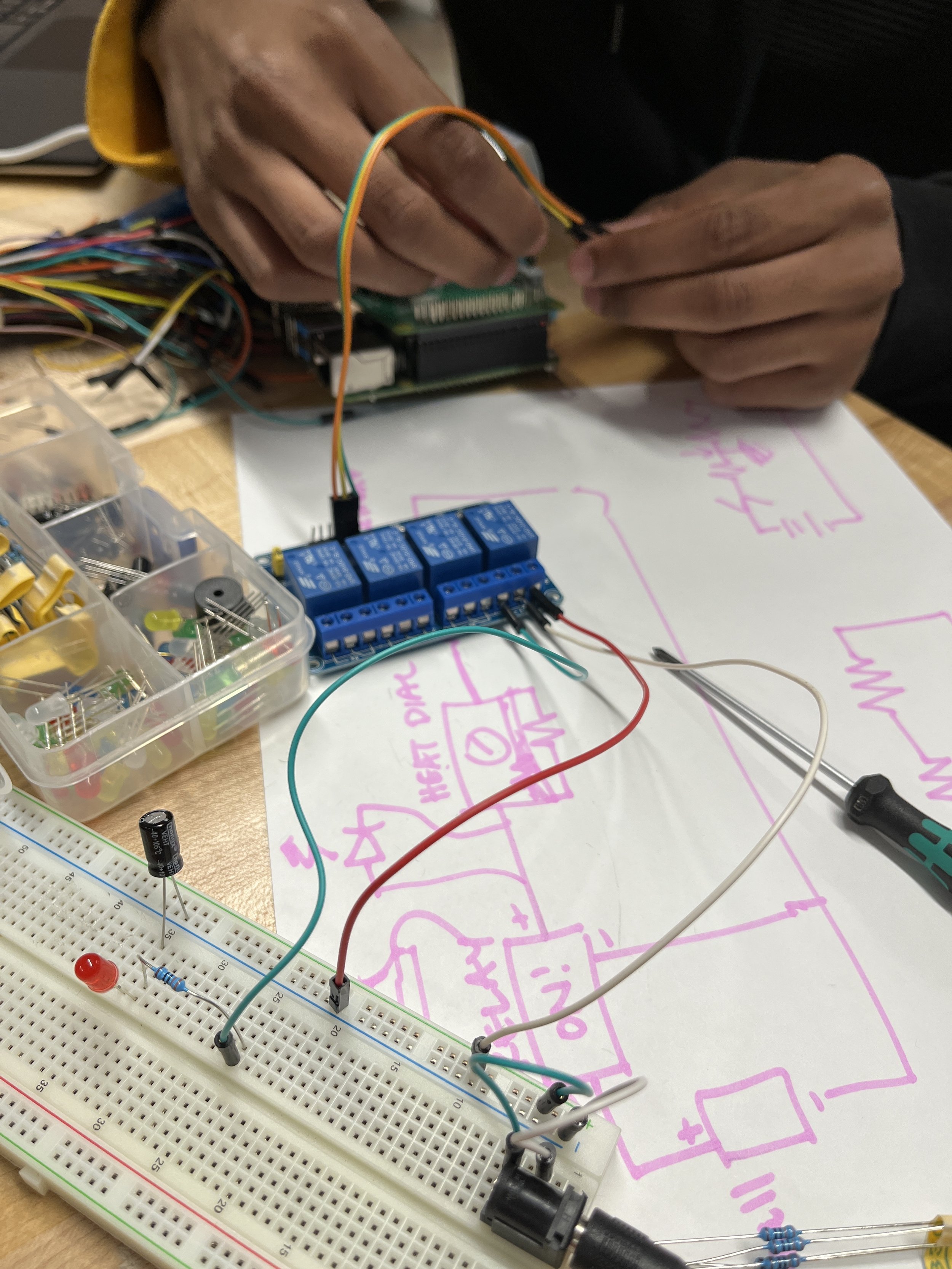
Since we had a working MVP, our goal towards the final deadline was to upgrade our mvp to work towards a larger oven that had a higher input current compared to our test oven. With this requirement, the relay module wouldn’t have worked the same, and instead we opted for a 25A Solid State Relay, that would arrive in time to begin testing with other subteams when they finished their respective solutions. The process for integrating it is still the same, all that is needed to be done is cutting the wire from the timer to power, and connecting the relay from the pi to the oven, so that Oven Control would have full control over when and what temperature the oven is turned on. My main contributions for the setup were coming up with the circuit diagram seen below, which shows the required placement of the relay in order to control the oven using airtable. We made use of the digi-key schematics for the relay module to determine the right connections for sending the signal from the pi to the oven. With airtable, we set the oven to preheat right before the mixing team to start, and when the baking is complete, to have the oven autonomously turn off. Our group was also tasked with selecting the oven for the final demo. I took charge in polling in the group’s choice of an oven, and letting our teacher know to order it.
We were also thinking about the oven door and how that would play into the system. Talking with the load/unload group, we proposed potentially lifting the oven door using a two motor pulley system, where one pulley pulled the door out 45 degrees, and another pulley would lift the door open. This would be the case where the oven would be in an upside down configuration. I worked with the mechanical and systems engineers to figure out different configurations for the pulleys to try and open the door. However, discussions with load/unload team led to us scrapping this solution, as the placement of the load/unload robot, would hit the pulley system. We then opted to just remove the door using metal shears, and decided to bake the cake with the door gone.
We also had to consider the placement of the oven rack in relation to the rest of the robots for the other subteams. The load/unload team had constrain concerning the max and minimum height they could move their lift for loading and unloading the pan into the oven and frosting mechanism section. The frosting mechanism of the robot needed to be located so that it would be able to frost above the minimum position for the load/unload robot. The oven rack needed to be at a height so that the load/unload team could easilly load and unload the cake without tipping or interferance from other systems. Myself and the systems engineers coordinated with the other teams to figure out the best configuration for all the systems to be placed. This sketch was made in conjunction with the Load/Unload team PM Kate.
To place the oven above the frosting mechanism, myself and the mechanical engineers designed a table that would support the robot so that the oven rack was at the desired height for the load/unload team.
Testing
It was essential that our system was ready within a week before the deadline, so that our entire class had time to test the full system together, to iron out any issues with the assembly process. Our main tests were to check a couple of safety factors:
Whether oven would turn on due to change in airtable condition
Whether the oven would turn off due to airtable
if the oven wasn’t generating smoke for heating of oven
The electronics were protected
We had some intial issues where the relay had touching the metal of the oven, and it blew out, so we had to replace it. We found that extending the wires using wire crimps would help with keeping the relay a safe distance from the oven. We also added heat sinks to prevent the relay module from overheating. It was great to test multiple times with the other teams, as we were able to promptly give feedback about placement of the load/unload, mixing , and frosting robots with respect to the oven.
Final Demo
Overall a great success, all the robots worked together using airtable to autonomously bake a cake, and frost an image of a tree onto the baked cake!
Cake Baking Robot MVP
In the first week of the assignment, our group was tasked with presenting with the most critical module for the oven control of the cake baking robot system. We showcased turning on the oven autonomously using airtable, with the oven integrated with a raspberry pi using a relay module. As project manager, I was responsible for working with the mechanical team and setting up the relay with the oven, and coordinating the interface for the cake baking system with the programming team. I also worked with the systems engineering to interface with the other subteams, to finalize on the dimensions for the oven, and the overall requirements for preheating the oven for baking.
Cake Baking Robot Systems Breakdown
For our final project, our entire class has been tasked with designing a cake making assembly, that will bake a cake in an oven, and frost an image onto the cake. I was assigned to be the project manager for the oven control group. My group will be tasked with designing method for autonomously control the settings for the oven.
Pick A Processor/Actuator
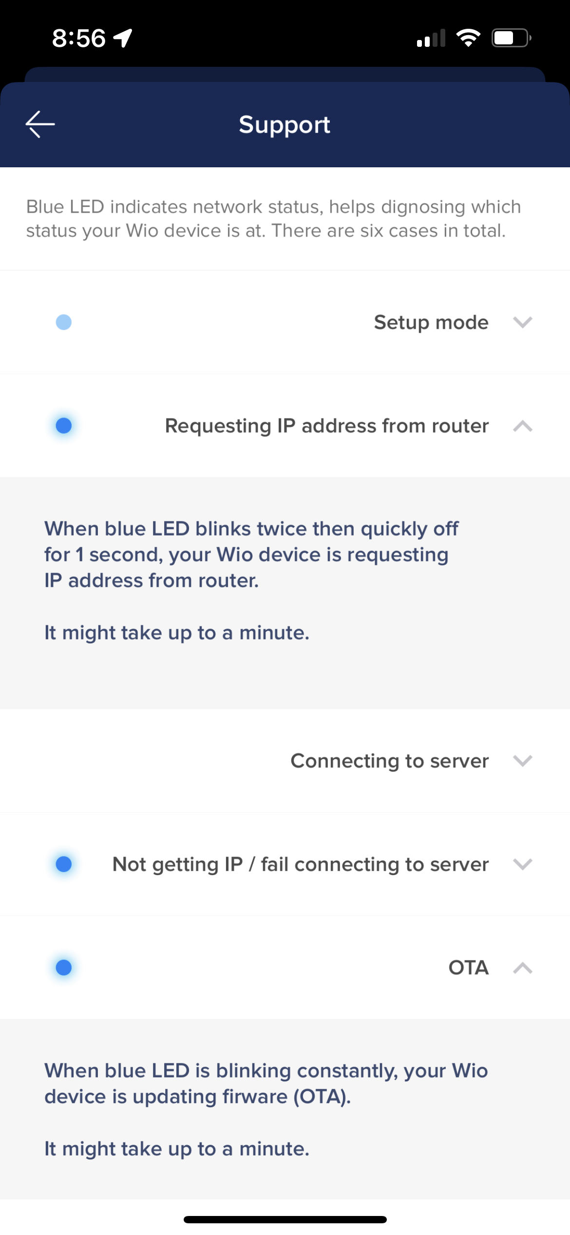
For our spring break, we were tasked with picking a random seeed studio processor and attached actuator from a box. I ended up picking a Wio Node and with it an attached LED Strip and sliding potentiometer. I had the simple goal of trying to setup the system so that i could light up the lights by sliding the potentiometer connected to the Wio Node. I found out the hard way that due to the Wio Node’s lack of a UART connection port, there is no way to program it with Arduino like I’m used to with other types of ESP8266. Wio promises that you can avoid soldering actuators and sensors onto this processor by using Wio’s grove modules, which are just 4 pin connections soldered with either actuators or sensors. This one was challenging to play with, as the only way to program it is using the Wio Link app in the App Store. There were issues with setting up the login for the app, and I found a fix for it being trying to use the processor using the school network, instead of my home network. With the wifi change, i was able to login into the app, and i went through the process to try and add my Wio Node device. Unfortunately, I believe all my school’s wifi networks were blocking the Wio Node internet connection, so i was never able to get it to connect. Just reading about the processor, there is unfortunately a large lack of documentation. Still in spite of this, i still found people in forums trying workarounds. This was a good project to try and understand one out of many processors we could use for our final project. I for one, will not choose to use this one, and will opt for an ESP8266, a processor I’m much more comfortable using.
Toothpaste Dispenser Robot
The goal of this project is to design a production line toothpaste dispenser. The goal was to get some additional exposure to using the Onshape REST API, OpenCV with the raspberry Pi module, and use tools to create a digital twin that could help us predict the results of our toothpaste dispenser robot. We were asked to first design a MVP of the dispenser, and then improve it to a final prototype.
The first week was spent designing a minimum viable product and using the onshape and the api it provides to control the robot using the digital twin. I had opted for a design in which if you constrain the roller, and instead shift the position of the toothpaste on a bed, that would be an efficient way of squeezing toothpaste for a robot. Unfortunately, this didn’t turn out the case, as this sliding method was challenging to model in onshape, and in practice, this method would squeeze out a fraction of a finger sized amount of toothpaste. For this iteration, i saw it as a great start in getting the Onshape REST API to work with my computer. It’s a fairly new tool that i’ve been able to use, but offers the great opportunity to make custom features in CAD design, and also be able to control different functionalities in my physical robot using OnshapeSpikePrime library. For the final version, with some additional help from partners we were assigned, I wanted to opt for a different solution by consolidating all our individuals ideas, reproduce the model in Onshape, and try my best to fully automate the dispenser.
For week two were off to a great start with the new mechanism. Instead of a sliding mechanism, we opted to have a wheel system using two servos that rolls on the tube over continuous increasing intervals to squeeze out a finger sized amount of toothpaste. We automated our toothbrush insertion using a servo that would move to the plane of toothpaste release, and then move upward when recieved, so another toothbrush could be inserted. I took the lead on redesigning the digital twin and getting flask to work, so we could show a live feed of toothpaste dispension for image processing, and simultaneously use Onshape REST API to control the mates in real time for our robot. The big challenges for this final stage were improving upon the squeezing mechanism, printing out the remaining toothbrushes worth of toothpaste to dispense, and using image processing to detect the toothbrush.
The new iteration of the mechanism required a significant amount of framing to restrain the motors in the z axis and y axis so they could move up and down using the power torque gear treads and gears for squeezing the toothpaste. Since there is a significant amount of friction on the toothpaste tube, we place tape on the tube to reduce the friction between the tube and the roller. In order to increase the squeeze amount, the method of multipe run throughs that I discovered in part 1, in which i ran over the toothpaste tube multiple times with increasing rotations led to squeezing out a toothbrush sized amount of toothpaste.
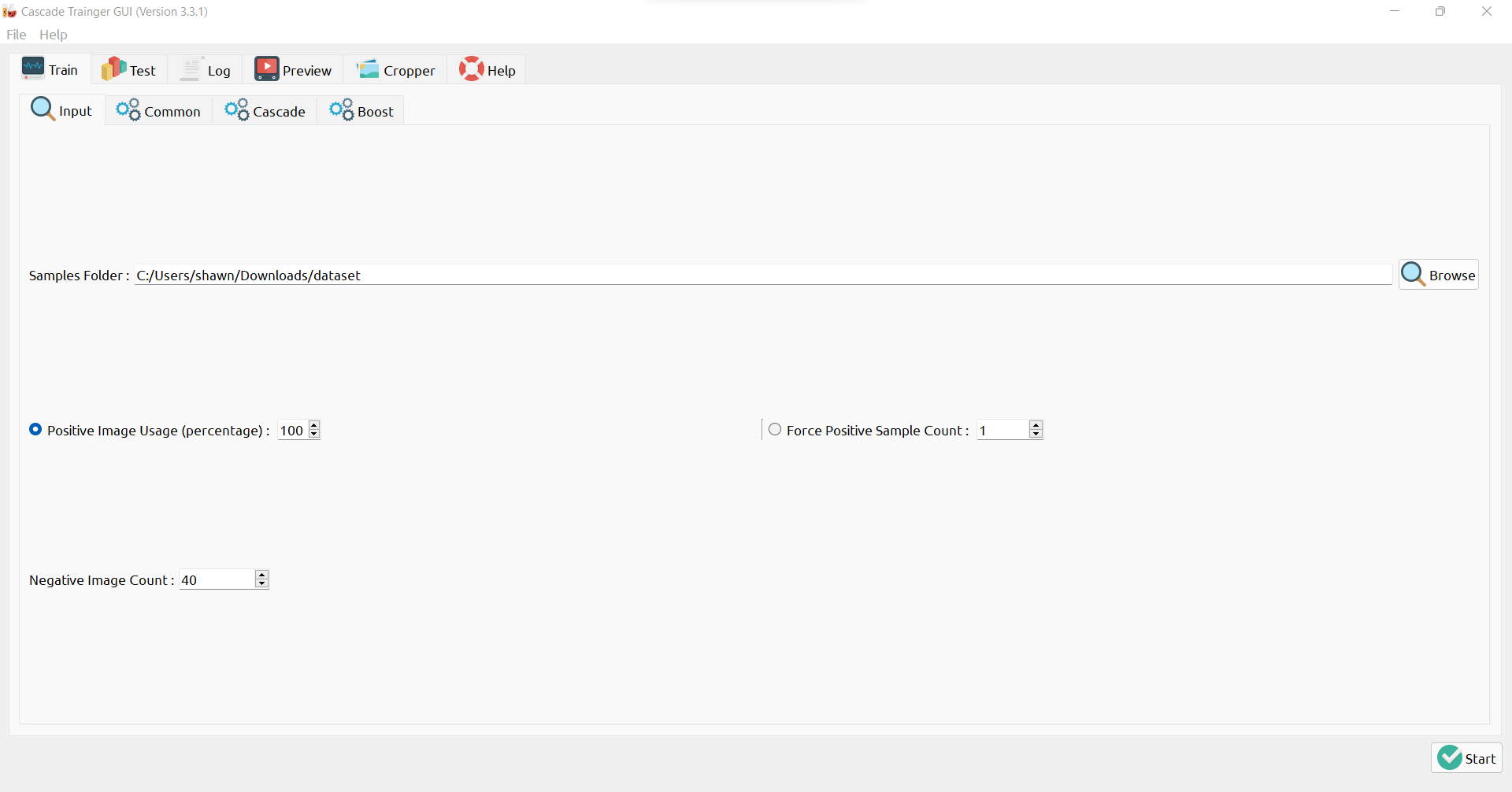
For image processing, I wanted to try and create a custom haar cascade file for object detection of the toothpaste on the brush. The haar cascade involves used a machine learning approach to object detection, where you can train the camera to detect exactly what you want in the live feed camera. I used the Cascade Trainer Generator GUI to present 40 positive(toothbrush only) and negative (non-toothbrush) photos to the trainer, and it would export a cascade file i could use with the OpenCV detectMultiScale to place a rectangle around the toothbrush head. Unfortunately this didn’t work out perfectly, and I believe it may be due to presenting a bad dataset to the GUI, or potentially using the wrong parameters for the detect multiscale. Even then, maybe an alternative method of color masking or marker detection would of been much simpler to use instead, so i’ll know to try that when i revisit this. The camera will still take a picture before releasing the toothpaste, and display the result of the toothpaste dispenser, before the servo retracts, allowing the user to retrieve the toothbrush. Then a display shows up indicating the number of remaining squeezes, which is calculated by taking the squeeze amount and subtracting it from the total volume that we took from the Onshape Part Properties, and use this to calculate remaining squeezes before tube is used up.
Overall, this was another great project where I was able to deep dive into different aspects of design, and being exposed to use the Onshape REST API opens the door to many opportunities to make new digital twins, custom CAD features, and create useful data plots for better understanding the systems we design in robotics.
Initial live feed test, ran a detect smiling script that uses the haar face cascade.
Test with updated assembly, at this stage haven’t yet figured out having the flask feed and the onshape api calls in the same python script.
Final test, where the dispenser works great and gives out a reasonable amount for the user to use, and returns the remaining toothpaste. Unfortunately the live feed stopped working and the automated toothbrush system never panned out using the camera. We also decided to use a set amount of continous rotations that would squeeze out our specificed squeeze distance.
V1 Test, able to make call to Onshape Api to control the servo for the Dispenser through rotating a control mate in the assembly.
Larger emphasis was place on redesigning the system for squeezing the toothpaste and showing the before and after result of dispensing toothpaste.
Data Dashboards
The goal of this project was to create a dashboard that could display something else aside from time. Our professor wanted us to use this project to incorporate REST APIs into our project. I decided to use the WeatherLink API to display the different conditions of the day given by the WeatherLink current weather API call, which returns a JSON that i can parse using python. I then used the current weather attribute to display different weather conditions, and displayed additional weather conditions based on checking the wind speed at the current moment. In addition, i also compared unix timestamps from the API and my own generated timestamp to then display whether it was currently daytime or nightime. It was fairly straightforward to using the requests library to make the calls. However, the API wasn’t updating consistently so when i would make the call three days straight, it would always return the condition of Cloudy. Maybe choosing an api that returned fluctuating data would of been useful to display.
I designed a clock displaying system in CAD then lasercut panels and 3D printed fins to construct the clock. I would love to revisit a different method for connecting the panels togethers, instead of using a hot glue gun.
This was a hard project for me mainly because I went in with the idea of making a music based API but found out i would have to pay to use it. I still believe i found a way to make it work, and i’m proud of what i made for the project.
Kibble Dispenser Robot
The goal of this project was to create a robot that woulf dispense kibble for a dog. Working with my partners Victor and Alp, we took into consideration designing a dog safe and non-threatning toy for Nellie to get kibble from.
The start of our idea was understanding that the dog used to test, Nellie, really likes to jump on platforms. Our initial idea was to half the dog jump on a platform that would then activate the kibble dispenser using a pressure switch. Then we realized the dog would be too big to jump on the platform, so it was altered to be a button the dog could press.
We then built a funnel system inspired by standing up kibble to store the kibble, and then created an attachment that would release the kibble onto the ramp for the dog to take the kibble from.
We coded an algorithm for the robot to wait until the dog pressed the button, and then the servo would slightly turn, releasing kibble through a small gap in the attachment, and the kibble would come down the ramp.
When testing the robot in person, we learned many insightful things. 1) If there isn’t any kibble on the jump platform, the dogs won’t be intersted in trying to press the button.
2) The kibble funnel and release attachment didn’t let enough kibble out. We didn’t have enough time to refine this design, and if we got a chance to revisit the project, trying different style funnels and attachments sizes would of definitely help.
Overall, Nellie was able to retrieve kibble from the dispenser by pressing the button, so I would call this a success!
Line Follower Robot
The goal of this project is to create a robot that can follow a black line, stop before hitting obstacles, turn at red lines, and stop at yellow lines on a path. The project required us to mainly use the Spike Prime’s color and ultrasonic sensor as ways to detect our environment.
Myself and my partner Teddy used a variation of proportional–integral–derivative control theory to tackle the first step of the assignment: having the robot follow a line. Using lumosity and color detection readings, we designed a proportional controller that could calibrate itself by reading color values and then generating a proportional controller using micropython. Using the PID Control Theory, we would fine tune gains based on trial and error testing the robot on provided line maps and determining that we needed low proportional gain values so the system wouldn’t have high instability when trying to follow lines.
For controlling the robot, we incorporated a state machine structure. Depending on the readings from the color , ultrasonic, and lumosity sensors, the robot would enter through different “states” and perform the specific tasks. This was an important way for us to outline and organize calibration, color sensing, and path travelling.
Top Spinner Robot
The goal of this project is to build a top spinner. Myself and my partner Victor wanted to make use of the tools such as a lathe and 3D printer to try an make the top. The top spinner was made solely with lego parts and the Spike Lego kit. We wanted a top with a low moment of inertia and a wide body so it could spin fast. We took inspiration from the Inception movie top spinner for our model. A test assembly was generated before we designed it. The top spinner was made from just playing around with the gear ratios until we had one that would help to move the spinner fast with a lot of power. The spinner was manufactured with the machine shop lathe.


